The Best Strategy To Use For Kubota Attachments
Way in the kind of a pair of spaced cylinders E forcefully raise the elevatable members by exerting a force between the elevatable frame member A and a tiltable ground engaging frame F upon which the elevatable frame member is installed. The front end loader, broadly designated at 10 in the illustrations, might be in the form of any ideal working vehicle.
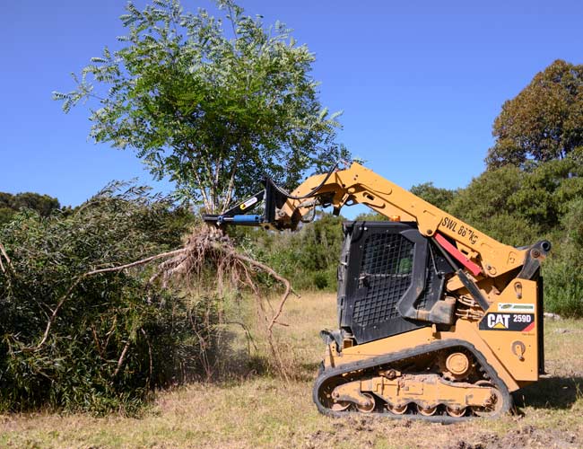
A cab is offered an operator that includes a front shield member 13 which might be of expanded metal which is effectively braced as at 14 to safeguard the operator, and yet permit the driver to see therethrough for carrying out the tree pulling operation. The normal transversely spaced arms 15 are pivoted on the chassis and extend forwardly and downwardly therefrom, while an intermediate part has pivotal connection as at 16 to the piston rod 17 of a cylinder 18. Kubota Rock Bucket.

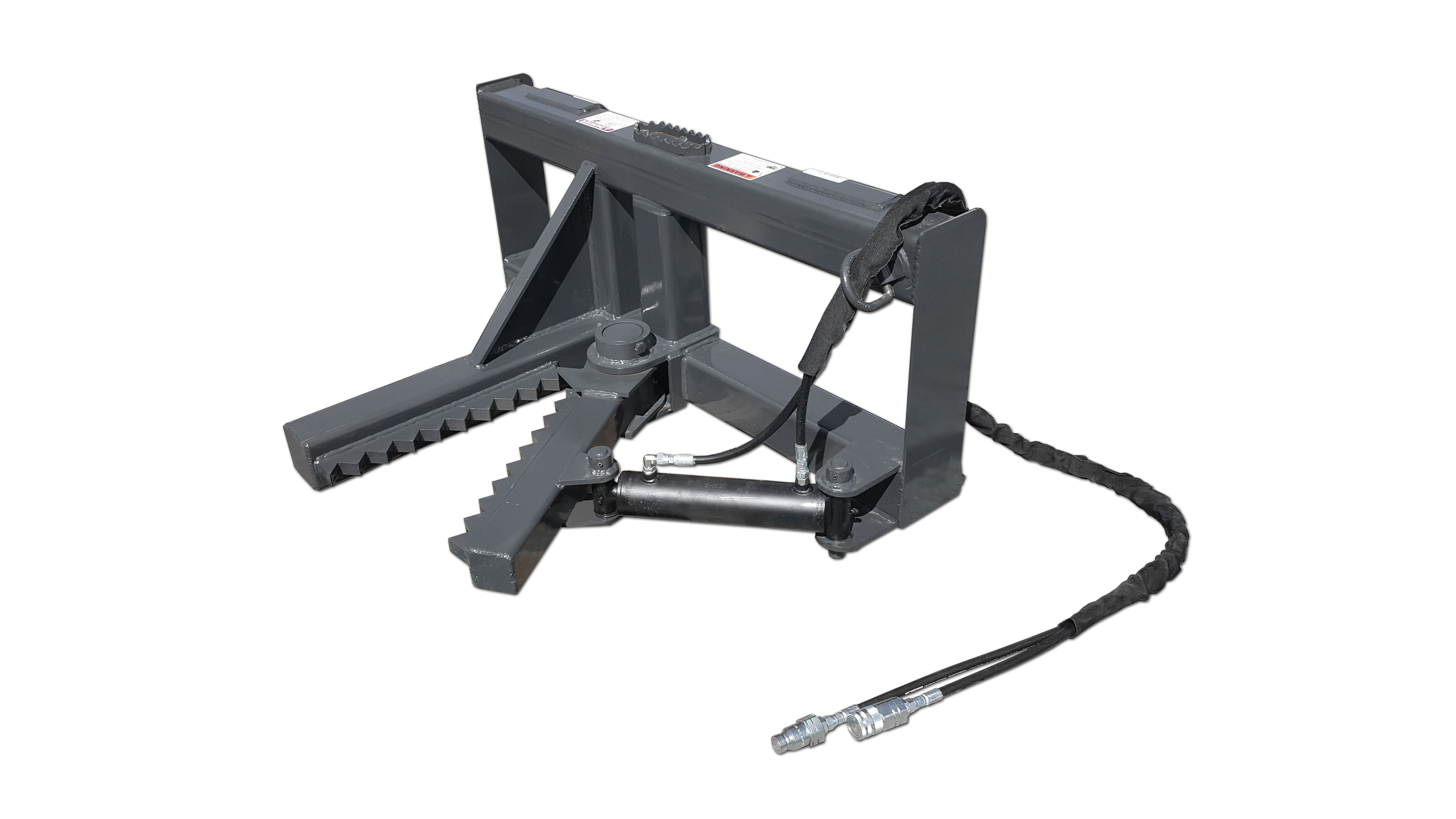
The piston rod 21 carried by the piston 19 is pivotally connected as at 22 upon a set of spaced fixed frame members 23. The elevatable member A is provided in the kind of a frame member having considerably rectangle-shaped frame supports 24 which specify at the front, an outwardly extending diverging member 25 forming a notch or V-shaped part for receiving a part of the trunk of the tree above the V-shaped gripper.
Mounting ways are attended to connecting the gripping way B in depending relation and such are shown at D. The inwardly forecasting blade C is finest highlighted in FIGS. 2 and 6 and includes a sharpened edge 26 and flat blade part 27 which is integrally protected to the thickened wedging members B, managing an upwardly extending wedging surface area 28.
The mounting method D includes essential connection as at 31, upon spaced installing plates 32 for attachment to the upright linkage 33 which has critical connection as at 34 with a forward portion of the elevatable frame member A (kubota skid steer attachments). The installing method D is further highlighted as consisting of a compressive assistance frame part 35 which has spaced critical connections 36 upon the tiltable ground engaging frame accessory F.
Getting My John Deere Attachments To Work
5, when the frame A is raised the gripper swings upwardly and outwardly in an arcuate course triggering the tree to swing rearwardly pivoting about the gripping indicate rest in the notch formed by the member 25 above the support put in by the gripper. The attachment frame F is pivotally carried as at 37 upon the totally free end of the arms 15, and includes upright transversely spaced frame members 38 and lower forwardly extending frame members 39 carried to form a substantially L-shaped frame (john deere tractor attachments).
The shoes 40, ideally have upwardly tapering ends 40a for facilitating movement thereof along the ground preparatory to engagement of the tree and actuation of the spaced cylinders E which powerfully raise the elevatable frame A by putting in a force in between an end part thereof and the tiltable frame F.
It needs to be kept in mind further that the wedging members B and the complementary inwardly extending blades C are arcuate and taper upwardly from the area of essential accessory at 31 toward a complimentary end as detailed at 45. FIG. 7 shows a modified kind of the development including additions and improvements.
5. While transporting over particularly rough terrain the tree in some cases revokes the puller head and ends up being uncontrolled requiring a time-consuming operation of gaining back control and later releasing the tree for disposition as the delivery to the desired place. A holding mechanism or grabber has been constructed which consists of a set of opposed arms 48 and 49.

The arms are pivotally carried on an installing bracket 50 and opposed ends of the arms 48b and 49b are supplied with appropriate essential connection to a double-acting cylinder 51 brought by the mounting bracket 50. The mounting bracket has a bifurcated, rearwardly extending support 52 which pivotally gets a link 53 which, in turn, has critical connection as at 54 (FIG.
The 30-Second Trick For Kubota Attachments
A second parallel link 55, spaced rearwardly of the link 53 has comparable essential connection to provide a regulated favorable movement for the gripper suggests. A cylinder 56 has essential connection with the linkage means and with the frame A so as to manage the forward and rearward motion of the gripper means.


7 rather than curved and have stiff connection by repaired linkage members 57 and 58 which have rigid connection with the wedging members, in addition to the lifting frame A. The cylinders E have pivotal connection with the frame A and with the ground engaging frame F. The lifting frame A and the rigidly carried wedging member B have pivotal connection as at 59 with a standard 60 which, together with the ground appealing frame F froms a supporting frame.

The lifting frame has pivotal connection as at 61 with the arm 15 of the vehicle. The ground appealing frame has a bigger foot or runner 62, and in order to assist in removal of the lifting device and lorry over rough ground from which the tree has actually been gotten rid of, a bridging roller 63 is rotatably installed as at 64 on a part of the supporting frame adjacent the vehicle.


Spaced cylinders E include piston rods 46 which have critical connection as at 47 the forward portions of the frame members A. Kubota Attachments. It ought to be observed in FIG. 1, that the tree might be nestled when in the position revealed in FIG. 5 in the diverging notch formed by the members 25.

This is achieved by formation of a ledge within the adjacent compressed tree fibers gripped by the wedging surface area 28 formed by the wedging members B. It is also essential to keep in mind that a considerably vertical lifting force may be successfully applied by strong engagement of the accessory or tiltable frame F with the ground permitting the fluid ran cylinders E to exert a force in between the elevatable frame A and the ground.
have a peek here bobcat auger for sale kubota b7000 attachments